If the wires to the TTS are reversed, the TTS will short battery voltage to ground whenever the TTS on on and the ignition switch is in the start position. See pinout of the TTS below:
View attachment 72466
When you say it does not start, what exactly does it do? Does the starter not run? Does the starter run, but the engine never catches? I assume you mean the former. In
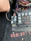
this thread you showed what appears to be a hard start relay installed by a previous owner. You should concentrate your search around this relay and trace out the wires.
Terminals 85 and 86 on the relay connect to the relay coil (look for terminal numbers embossed at the bottom of the relay, or search for "Bosch relay pinout"). One of these terminals (preferably #85) needs to be connected to ground. The other (preferably #86) needs to be connected to the "start" wire from the ignition switch. This wire will have battery voltage when the ignition switch is in the "start" position, no voltage otherwise. In stock form, this will actually be two wires (one RED and one RED/BLK) terminated into a single female 1/4" connector with a white plastic housing hanging out in the engine compartment in the starter neighborhood. Do not separate the RED and RED/BLK wires; they will both go to the same terminal on the relay
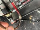
The relay switch contacts are brought out on terminals 30 and 87. One of these (preferably #30) should be connected to unswitched battery voltage. Typically this is taken from the stud on the starter that has two fat wires going to it. The other, preferably #87, should be connected to the trigger port on the starter. Your relay may also have a terminal numbered 87a; nothing should be connected here.
Make sure the transmission is in neutral when you play around with this; we don't want your next post to be about physical damage or bodily harm...
Hi Bjorn,
That’s for the detailed answer. The car is acting like it’s getting zero fuel on start so it doesn’t catch.
I got it to run great for 2 days with a ton of hot, warm and cold starts and then a hot start didn’t work. I managed to break off the left side of the connector on the tts while poking around and took the other side off when I brought it to the parts shop to see if their part would work. I drove the car home about 20 miles after splicing it in. I Tried starting it in the drive way as soon as I got home and it worked and the next morning I got nothing. After resting it for an hour or 2, the first try sounded like for a split second it wanted to try but then all I got was the sound of just the engine turning. It’s been that way since but after I spliced into the harness more for the tts I lost the ground to engine and ground to body. The attempt to start does nothing more than the basic I’m not getting any fuel - so nothing. In addition, the cold start injector which was getting 8.5 volts is getting zero. The tts connector has gotten zero all along instead of 12 volts. I
Basically have no clue at this point and will retrace the above. I don’t think the wires on the hard start were mixed.
I guess my question is if the wires to the tts were swapped, did I ruin the part and if I try to swap then and they are correct, will I ruin the part. The tts is impossible to find.
My guess is that the car started because of it cooled down, it would start. Perhaps it was above 35C but cooled down enough so the cold start process didn’t kick in. That’s why the car got me home but wouldn’t start the next day.
Should I swap the wires on the tts and see what happens or could that make matters worse?
If the wires to the TTS are reversed, the TTS will short battery voltage to ground whenever the TTS on on and the ignition switch is in the start position. See pinout of the TTS below:
View attachment 72466
When you say it does not start, what exactly does it do? Does the starter not run? Does the starter run, but the engine never catches? I assume you mean the former. In
this thread you showed what appears to be a hard start relay installed by a previous owner. You should concentrate your search around this relay and trace out the wires.
Terminals 85 and 86 on the relay connect to the relay coil (look for terminal numbers embossed at the bottom of the relay, or search for "Bosch relay pinout"). One of these terminals (preferably #85) needs to be connected to ground. The other (preferably #86) needs to be connected to the "start" wire from the ignition switch. This wire will have battery voltage when the ignition switch is in the "start" position, no voltage otherwise. In stock form, this will actually be two wires (one RED and one RED/BLK) terminated into a single female 1/4" connector with a white plastic housing hanging out in the engine compartment in the starter neighborhood. Do not separate the RED and RED/BLK wires; they will both go to the same terminal on the relay
The relay switch contacts are brought out on terminals 30 and 87. One of these (preferably #30) should be connected to unswitched battery voltage. Typically this is taken from the stud on the starter that has two fat wires going to it. The other, preferably #87, should be connected to the trigger port on the starter. Your relay may also have a terminal numbered 87a; nothing should be connected here.
Make sure the transmission is in neutral when you play around with this; we don't want your next post to be about physical damage or bodily harm...
Hi Bjorn,
Thanks for the detailed answer. The car is acting like it’s getting zero fuel on start so it doesn’t catch.
I got it to run great for 2 days after replacing the thermostat, fuel pressure regulator, the spark plugs spark plug wires, rotor, distributor cap and coolant temperature sensor- with a ton of hot, warm and cold starts and then a hot start didn’t work.
I managed to break off the left side of the connector on the tts while poking around and took the other side off to bring it to the parts shop to see if their connector would work.
I drove the car home about 20 miles after splicing it in. I Tried starting it in the drive way as soon as I got home and it worked and the next morning I got nothing but it tried to start for a split second. Now, it just won’t try at all. It’s clearly getting no fuel On cold start.
After getting ride of the exposed wires in the harness where the connector was spliced in for the tts, I lost the ground to engine and ground to body - most likely I wiggled things around too much.
In addition, the cold start injector which was getting 8.5 volts is getting zero now. The tts connector has gotten zero all along instead of the 12 volts I expect.
Basically have no clue at this point and will retrace what you noted. I don’t think the wires on the hard start were mixed but given that both wires of the tts are white, they could have been but I tried to keep the wires on the same side as they sat. Can I test each wire with a multi meter to see which is the G side?
I guess my questions are, if the wires to the tts were swapped, did I ruin the part and should I try to swap the wires as they are now? I’m showing an open circuit using my
ECT 3000 the way things are now. So does that mean I did swap the wires which caused 0 volts to go through the connector?
I’m getting zero voltage to the connector so if I swap the splice should I get 12 volts to the connector? And if the wires are crossed will I ruin the TTS?
What started all this was the car would not start when warm - even if I drove it for 2 blocks and tried to start it. After resting it, it would start. Sometimes, depressing the gas to the floor would do the trick.
Now, it just doesn’t catch at all when cold.